

Create Custom Tool Operators With Geometry Nodes
Use a unique set of nodes to create custom tool operators in Blender 4.3

So far we’ve covered a fair bit of Geometry Nodes as they pertain to procedural geometry setups. From field basics to loops and attributes, we’ve established a base set of knowledge to get us started in Geometry Nodes. However, the important thing to remember is that these setups have all been static setups. All of our node groups up until now have been static evaluations that are applied to single objects. But what if I told you that there is a whole other side to Geometry Nodes that I haven’t told you about?
With the release of Blender 4.2, the developers gifted us a great set of features and new nodes to create Node Tools. You can think of them like you would the Transform operator or the Bevel operator that you would use when you manually model. Except with Node Tools, you define the logic and actions that an operator executes. So without further ado, let’s get into the meat and bones of Geometry Nodes’ Node Tools.
Custom Operators
The core idea of Node Tools is extremely similar to the regular operator tools you'll find on the toolbar. Select your geometry, make any additional sub-selections for specific domain entities, and then activate the Node Tool. You even have the ability to create the configuration window that allows you to adjust the operation you just performed. They’re so similar that you can even recreate the toolbar operators yourself in a custom node tool.
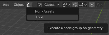
Creating a custom Node Tool is as simple as changing one setting in the node graph. In the top left side of node graph window, you’ll see a drop-down menu that should initially say “Modifier”. This menu indicates which mode the node graph is currently in. If you choose the “Tool” option your window won’t noticeably change, but you’ve just moved into a whole new section of Geometry Nodes.
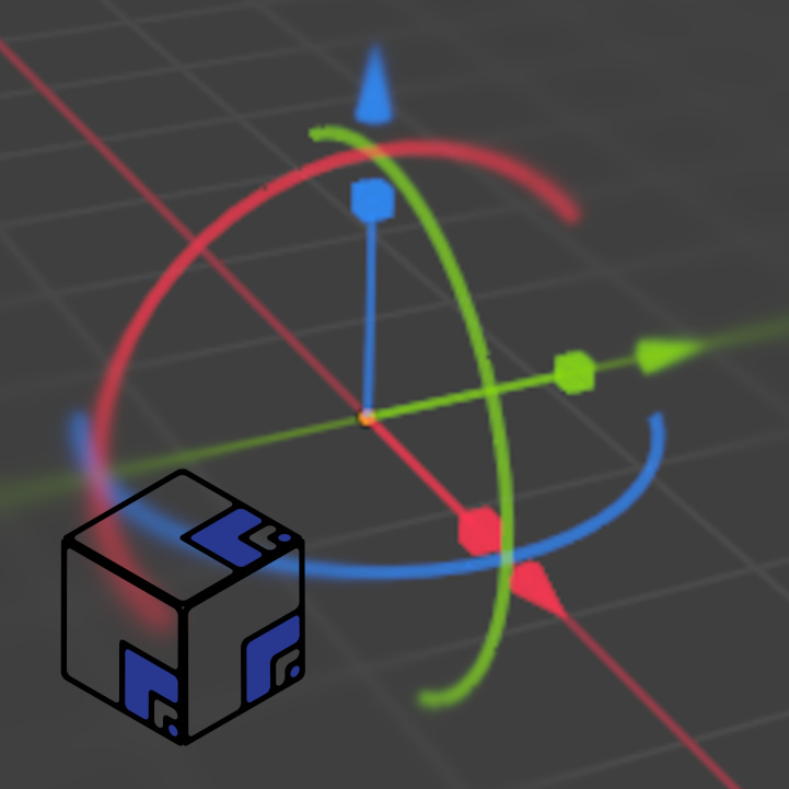
The biggest difference you’ll notice is that creating a new node group in the “Tool” mode doesn’t create a modifier on the primary geometry you’ve selected. Instead, a Node Tool exists inside of the Blender file itself rather than needing to be attached to any object to be seen. If you go to a Viewport window, you’ll find that the top bar now has a new icon on it, and within will be an operator that executes the Node Tool you just created.
Finally, the last point of general discussion is the appearance of three new drop-down menus at the top of the node graph. These are options that give you control over how the Node Tool will execute.
The Types menu lets you choose between Mesh and Hair Curves mesh types.
The Modes menu determines whether the Node Tool will operate in the Object mode, the Edit mode, or the Sculpt mode.
Options only has one choice, which toggles whether the node tool needs to wait for a mouse click before executing its operation.
Unique Tool Nodes
Making a custom Node Tool isn’t that exciting on its own though, so what options do we have available to help us change that?
We have access to a whole unique group of nodes that aren’t available to us in the “Modifier” mode. They mostly pertain to interacting with the 3D Viewport, but there are some other neat options that give us ability to control how the Node Tool executes its logic. Before we get into specific nodes, it’s also worth mentioning that there are a couple of nodes that are not available to us in the “Tool” mode, namely the Viewer node and the Simulation Zone.
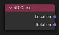
3D Cursor Node
To start us off, the 3D Cursor Node provides a Location vector value and a Rotation matrix value for the location and rotation values of the 3D Cursor as it is in the scene.
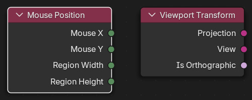
Mouse Position Node & Viewport Transform Node
These next two nodes start to get a little more tricky unless you understand how 3D scenes are created. To give a quick summary, we work in 2D environments on computer monitors. Our mouse occupies that 2D space at exact positions. By calculating the position of our mouse in XY coordinates we can then interpolate that value into how the scene’s viewspace is being experienced. There’s a lot of math that goes into this, so it’s just easier to link back to a previous article that explains how 3D scenes are displayed.

For now we’re just jsut concerned with how the nodes function. The Mouse Position Node is able to give us the X and Y coordinates of our mouse in a 3D viewport along with the size of the viewport window. In a similar vein, the Viewport Transform Node provides a number of different values for what view our viewport is set as.
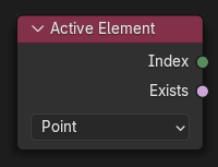
Active Element Node
Since our node group is used as a tool instead of a static modifier, we get to interact with the mesh data of geometry rather than just reference it. The Active Element Node allows us to select multiple entries in a domain and specifically reference the last (active) entry’s Index values. This works for the points (vertices), edges, and faces of any geometry.
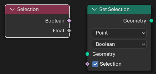
Selection Node & Set Selection Node
The Selection Node returns a boolean value that indicates whether a specific entry is currently selected or not. To compliment the Selection Node, the Set Selection Node allows us to dictate what geometry is selected by a specified boolean value. They are related, but not necessarily required for each other.
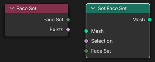
Face Set Node & Set Face Set Node
Taking a page from the Sculpting toolkit, the Face Set Node returns the Index value of the face set that each individual face is apart of. Again, the Set Face Set Node compliments this by allowing us to specify what face set geometry should have. Face Sets are a way to group faces and quickly allow artists to hide/mask parts of meshes.
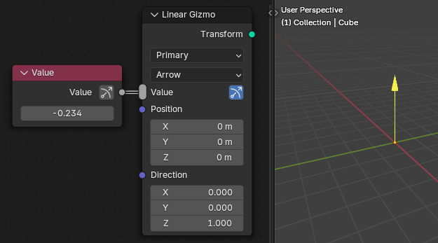
Gizmos
Finally, I have to mention Gizmos. Introduced in 4.3, Gizmos are viewport objects that allow you to directly adjust the results of Node Tools. Just like you can use a Gizmo to move, rotate, and scale an object in the viewport, you can do the exact same thing for your custom Node Tools. I won’t be using them in my example, but I’ll leave a link to the official Blender developers showcase of their capabilities below1.
Tutorial
Instance On Viewport Selection
Instead of a step-by-step guide, this tutorial will be about the process that occurs when a Node Tool is created and used. A picture of the Node Tool’s node graph will be provided, however it is mostly lifted from a video by Blender Studio that I’ll provide in the next section.
What Is Happening
We want to add one object to another by placing it through the viewport. While we could try and pick a vertex to instance this object on, using a Node Tool and the viewport allow us to place the object exactly where we want it.
The Node Group
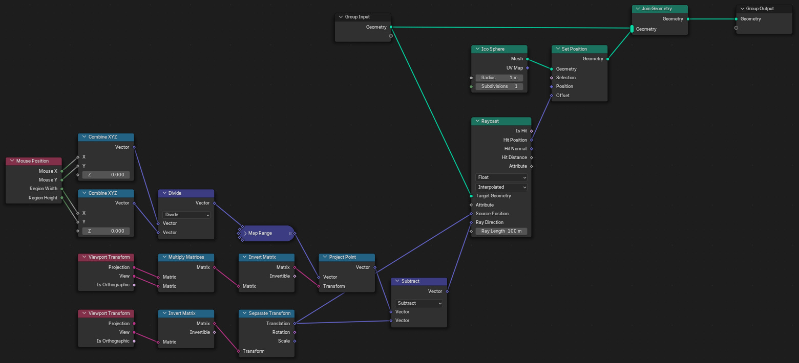
First we calculate the position of the mouse in the viewport.
Because we’ve selected “Wait For Click” in the Options menu, the Node Tool won’t execute immediately and will wait until we click to execute the node logic.
Then we figure out the exact position that our mouse is located at in the 3D viewport space.
Again, the initial node setup is lifted from the Blender Studio video, but it’s fundamentally the same process as I described in the previous article I mentioned above.
Finally, a Raycast node is used to calculate where the point our mouse is located at on our inputted mesh, a flat plane in this example (although it could be any mesh object).
The exact point location (as dictated by the Hit Position output socket of the Raycast node) is used to spawn an Isosphere mesh object on the plane object. Then both objects are merged together and outputted through the Group Output node.
Outcome
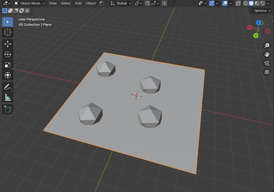
The result of running this Node Tool is that an Isophere is added to the plane object at the point where we click. By utilizing the unique nodes available to the “Tool” mode of Geometry Nodes, we’re able to interact with geometry by creating custom operator tools.
Blender Studio: Mesh Fracture
This tutorial covers an adjacent application of the above tutorial. It’s application goes more in-depth on the explanation of calculating the exact point a mouse-click is located at.
Outro
In this tutorial we covered a brief introduction to Node Tools, outlined the unique nodes that are only accessible in Tool mode, and covered a simple method for getting the mouse position in a viewport and spawning objects on that point.
Next week we’ll be looking into weaving Animation to Geometry Nodes setups, and on February 17th supporters will receive a How-To on Procedural UVing. Be sure to subscribe if you haven’t so that you don’t miss either of these articles!
- Adam
Gizmos (And More Blender 4.3 Features) - Blender Developers