

Art, Technically: Graphics Rendering
MipMap #042: Vertex Shading and Rasterization

Today, the bare minimum we expect out of computers is running applications at a 1080p resolution with a 60 Hz refresh rate. It’s become the standard for gaming, productivity applications, and even some forms of viewing content. But what does 1080p at 60 Hz actually mean?
A screen’s resolution is the amount of pixels that displays the computer’s outputs. 1080p is shorthand for 1920 x 1080, 1920 pixels horizontally and 1080 vertically. Altogether these add up to 2,073,600 pixels for one screen. Each of these pixels is a combination of 3 colour values corresponding to the red, blue, and green cones we humans have in our eyes. By increasing and decreasing the intensity of those three core colours, we can make each of the 2,073,600 pixels display a different colour.
When we’re talking about the refresh rate (60 Hz), we’re looking at the amount of times that those pixels get updated every second. A refresh rate of 60 Hz is 1 refresh (update) every 0.0166 seconds, or 16.6 milliseconds. Applying 60 updates every second to each pixel comes out to a ridiculously high amount of calculations that we are accustomed to with our “bare minimum” expectation of a computer system.
The crazy part is that the monitor or television being able to update that many times isn’t even the hard part. Instead, that goes to the software that the computer processes to be shown on the monitor. Because it’s not just the monitor that is updating the pixels, it’s the computer sending what is shown on each update that is the bottleneck computers face.
1080p at 60 Hz is the baseline that we all expect because modern day computers are able to (at a minimum) output that amount of calculations and updates for the software we use on them. Yet, not all software outputs the same performance. Basic text editors require nowhere near as much computing power as a game does.
So how do they differ? What is so different about rendering polygons in an animated scene than displaying a still image? Over the next several issues of MipMap, I want to explore what actually happens when we make art. This issue will be focused on the basics of how geometry is rendered, but as we progress we’ll be covering shaders, lighting, file formats, and the means in which modern computers render everything from real-time experiences to pre-rendered animations. We’ll still be going over art, but this time it’s just a little bit more technical.
The Four Spaces
You’ve heard me talk about this before, but geometry is just a collection of vertices joined together to make faces that are separated by edges. Each vertex has an X, Y, and Z coordinate, and faces have textures applied over them. However, this is where my previous spiel stops and my recent learnings begin.
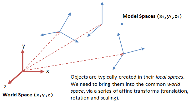
Those X, Y, and Z values for each vertex exist in a geometry’s local (or model) space, where each vertex’s coordinates are kept in relation to each other. Scenes are the next step up, containing a collection of individual geometries in relation to each other. Scenes have a world space, with their origins located at 0, 0, 0 on the XYZ axes. Geometries that exist in a scene are given a rotation, translation, and scale value to dictate how they are positioned in the world space. So together we have our geometry existing in both a local space and a world (scene) space.
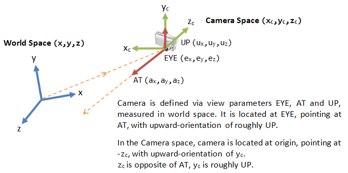
The next level of complexity is when we introduce a camera or viewport into the scene. Like geometry, a camera is just another object that is present in the scene, complete with it’s own space. However, instead of being a local space where vertices are kept in relation to each other, the camera space dictates what is and isn’t in view. If an object isn’t within the camera’s view, than it isn’t apart of the camera space. This is controlled by setting a camera’s resolution and field of view alongside where a rotation and translation value to determine where it is positioned.
Viewports in DCCs work in similar ways, except their purpose is to let us view the scene rather than determine what is in view. Normally we don’t get to manipulate the resolution and field of view values for viewports, while rotation and translation are actively manipulated by moving the view rather than directly set.
The final step in how 3D graphics are assembled is by converting the objects (existing first in local space by themselves, and then with each other in world space) visible in the camera space to the screen space. Screen space is what is displayed to the monitor, translating 3D objects to a 2D image that is displayed on your monitor or TV. We’re able to convert objects into screen space by multiplying all of the values of our previous spaces together in order to display each vertex and face at the right location on a screen.
Moving geometry between those first three spaces are known as vertex shading, where we are determining what geometry is being rendered out. Moving everything to the screen space is known as rasterization.
Rasterization
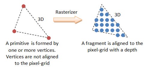
Now that we understand how everything in a scene relates to each other, the question is how do we determine what gets rendered and what gets omitted? While the camera space eliminates any geometry that isn’t in our line of sight, how do we know what geometry should be rendered up front or in the back?
The solution is using a Z buffer (also known as a depth mask) to assign a value to each vertex contained within the camera space. Since the camera also exists in world space, we know where it’s location is relative to every other geometry in the scene. Calculating the distance between a geometry and the camera allows us to assign a Z buffer value to each vertex on the geometry in question, which is then normalized to get us a value between 0 and 1. If a vertex’s Z buffer value is near 0, then the vertex is closer to the camera and likely gets rendered out in front. Likewise, if a Z buffer value is closer to 1, then the vertex is farther away and likely won’t be seen. This Z buffer value also gets interpolated across every face that the vertices make. If two faces clip, tham the section of each face with the higher Z buffer value get shown, which can lead to clipping as both faces intersect ieach other.
Now that we know what vertices and faces are going to be displayed on the screen we can begin figuring out how the two million pixels are going to display the contents of the scene.
A pixel is a single point on the screen, and since our geometry exists in a virtual environment it’s not always going to neatly fit into individual points. This results in a jagged, pixelated edge on geometries that are rendered to screens since the edges of faces only partially crossing a single pixel. This resulted is aliasing, the visual artifacting of geometry as faces were rendered on unique pixels. When computers weren’t as powerful as they were today, this was just how things were, and contributed to the blocky look of older games that couldn’t get rid of aliasing.
In more recent years though, anti-aliasing technology has come a long way, and is normally implemented to some level by default. While anti-aliasing can be implemented in multiple ways (each with their own benefits), we’ll stick to super sampling anti-aliasing (SSAA) in this article, which specifically relates to removing the noticeable pixel edges on displays.
The short and sweet explanation of SSAA is that if a face only partially covers a pixel, then a diminished shade of that pixel is applied instead of the full colour. This allows the edge to be softened, easing the jagged nature of the pixel. When calculating what the value of that diminished shade would be, each pixel is sampled at a specific rate, either 4x, 8x, or 16x, to determine what portion of the pixel is covered. The more samples that are covered, the less diminished the pixel shade will be.
SSAA isn’t the end all be all of anti-aliasing tech. Several off shoots use the same concept but in different applications to provide better results in their individual contexts. Multi-sample anti-aliasing (MSAA) is a GPU specific version of SSAA which is implemented directly into the GPU hardware, while full-screen anti-aliasing (FSAA) renders the scene at a much higher resolution to then down-sampling the image into the target resolution.
Next Week: Shading
Of course, there is still a lot more that happens in-between vertex shading and rasterization, but I might be going a little bit out of scope with it. This was just the first two steps of a rather involved pipeline, so I don’t want to fall in too deep before we can all form a starting idea.
If you’d like a better, more in-depth explanation than I highly recommend the webpage that I took all of my images from. This page is a full encapsulation of the basics of 3D graphics (alongside some code implementation to see what things actually look like. While this video also does a great job of giving an overview in video format. I used both of these links to help write the article, so credit where credit is due!
Next week we’ll be finish out the pipeline with Fragment Shading and maybe even get into proper Shaders! Stay tuned!
- Adam