

Assemble Your First Geometry Nodes
Intro to Geometry Nodes in Blender 4.3

Intro
The latest tool to enter Blender was the introduction of Geometry Nodes back in 2021. With it came the first truly procedural building tool fully open sourced to the public.
Yet, what do you know about Geometry Nodes? Do you know how to use them? What about how to actually setup your node graph? Maybe you didn't even know what a node graph is?
This tutorial is going to cover your first interactions with Geometry Nodes, from opening the editor for the first time all the way to adjusting values in fields and making the right node connections.
(If this article is cut off in your email inbox, please open it in a browser to view the rest! This is an issue with some email providers, not Substack or this publication.)
Geometry Nodes Editor
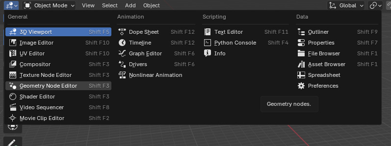
Accessing Geometry Nodes can be done in one of two ways, either through the default workspace panel at the top of Blender, or by changing an Editor's type to the Node Graph. Changing an Editor's type to Node Graph will replace the selected Editor with a Node Graph only.
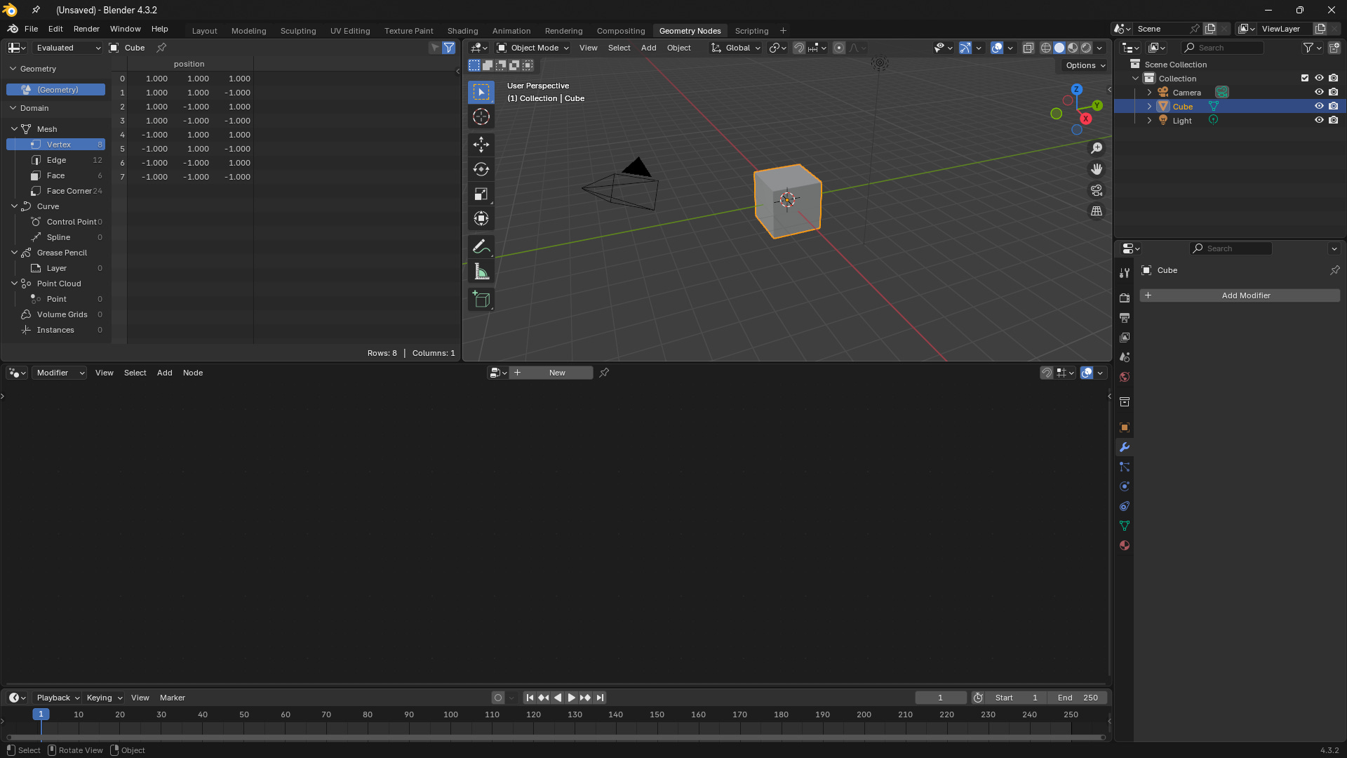
The default Geometry Nodes workspace contains (in order from top left to bottom right) a Spreadsheet Inspector, a Viewport, a Node Graph, and a Timeline. Some of these are more important to work with, while others are more optional. Here’s a brief run down of the individual components:
Spreadsheet Inspector
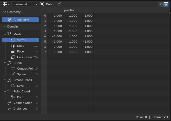
Details relevant attributes on every vertex, line, face, face corner, volume, and many more objects in the current geometry node group.
Viewport
Lets you see into the 3D scene.
Node Graph
Where the actual nodes are placed and connected.
Timeline
A slider that determine what animation frame the scene is on.
Hitting Spacebar will begin to play the scene at the scene's framerate.
Nodes
Within the Node Graph we have to make sure we have a Node Group active for anything to happen.
This is done automatically when you add a Geometry Nodes Modifier to an Object, or manually by selecting "+ New" button at the top of the Node Graph Editor.
Only the Active object you are selecting will have the new node group applied to it.
When a node group is created for the first time, you'll see a "Group Input" and "Group Output" node that are placed by default.
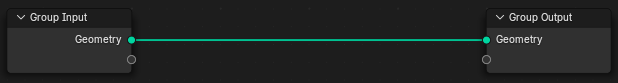
Group Input is the starting geometry before we do anything in the Geometry Nodes.
Group Output is the final results after everything we do inside of the Geometry Nodes.
We can place down any Node by either Right-Clicking and selecting "+ Add" for a list of all available nodes, or by going to the Add menu at the top of the Node Graph Editor.
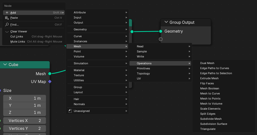
However, the fastest way to access the nodes is by using the Shift+A shortcut for this action. This will bring you straight into the node selection menu.
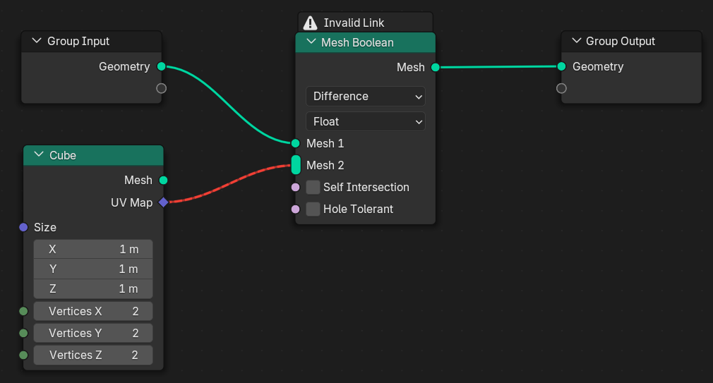
Fields Sockets
All Geometry Nodes will have Sockets1 on either the left, right, or both sides. Sockets can be click-dragged out and connected to other nodes to pass information to each other.
Some Nodes will have values you can adjust if a Socket isn't connected to it.
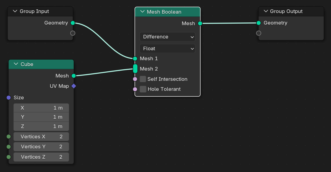
The "Cube" node in the picture above has adjustable values for the cube size values along with the number of vertices for the X, Y, and Z resolutions.
The "Mesh Boolean" node in the picture above has a selection box for both the "Self Intersection" and "Hole Tolerant" Sockets.
Sockets flow from left to right, meaning that you can't connect a Socket from the end of a node group back into the beginning or back into itself.
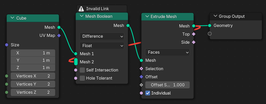
Not all Sockets will connect with each other. Pay attention to the Shape and Colour of each Socket. The connecting line will turn Red if the two Socket types are incompatible.
Workflow
Working with Geometry Nodes is a straightforward process. Once you’ve created your Node Group, you’ll be following this pattern:
Import / Create a Mesh
Add An Action / Manipulator
Connect The Mesh To The Action
Adjust Any Values
Repeat
Finally, once you’re satisfied with what you’ve created, you’ll connect any resulting sockets (containing any meshes or other field types) to the Group Output Node.
Example
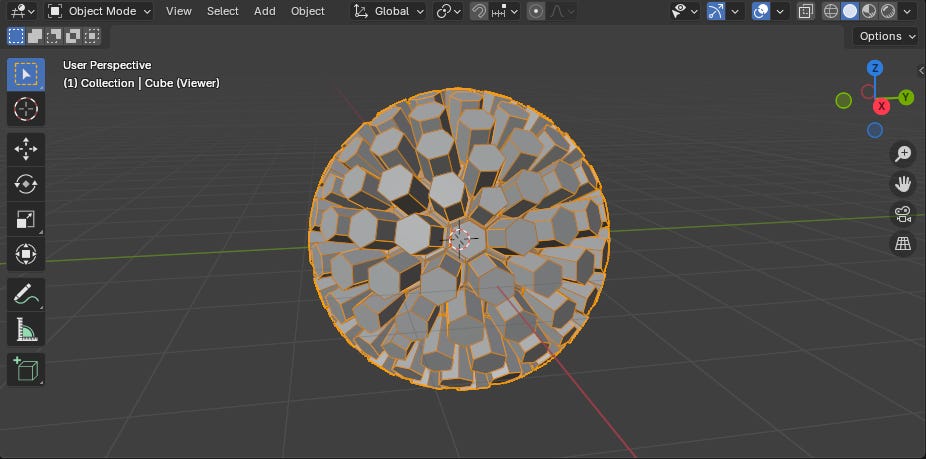
Lets turn the Default Cube into a hollow hexagonal ball, something that would be a bit too much to do by hand, but is a fairly simple task with Geometry Nodes.
Start
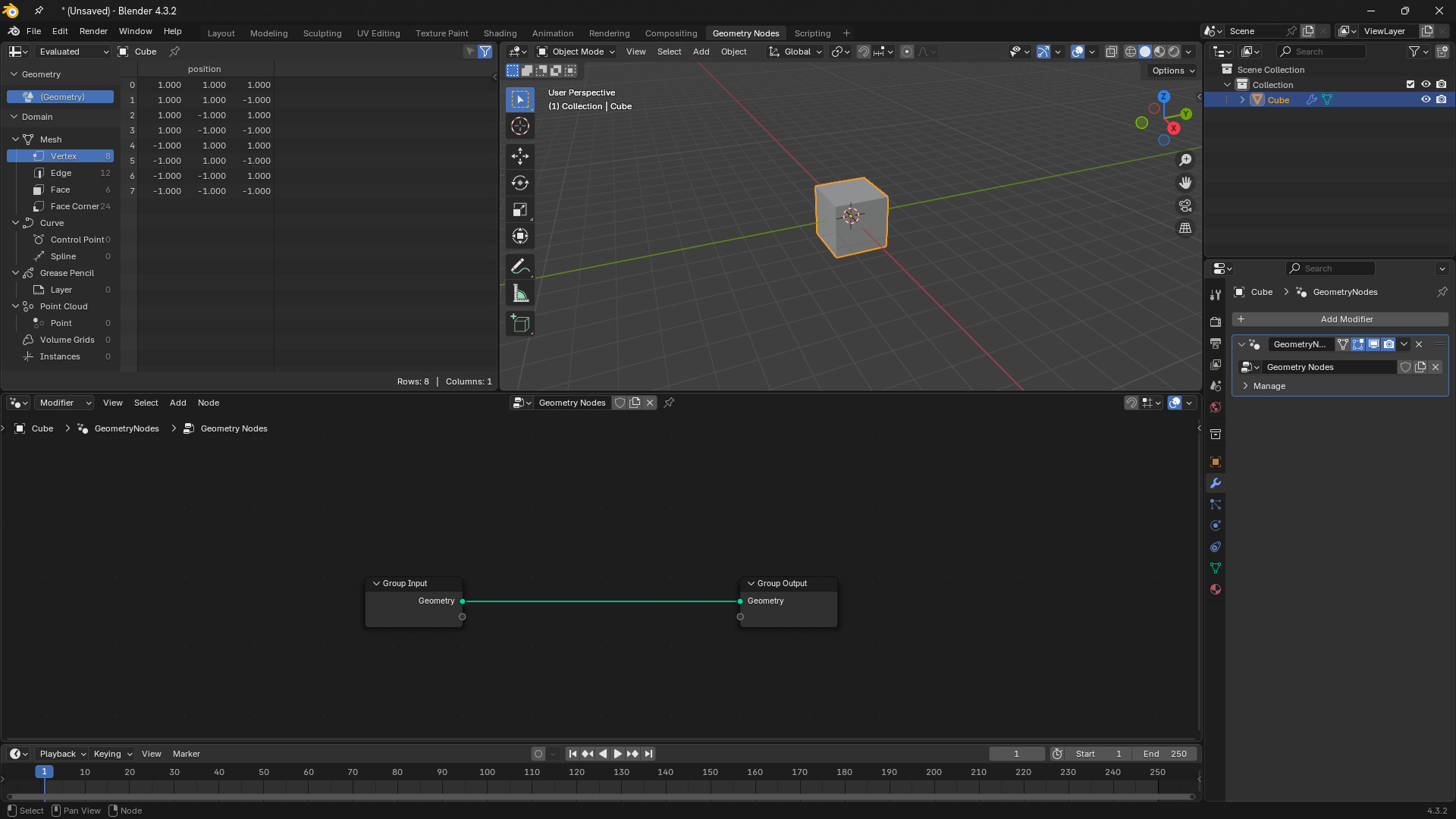
Let’s start with an empty scene, and create a default Geometry Node setup on the Default Cube.
Step 1
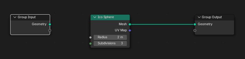
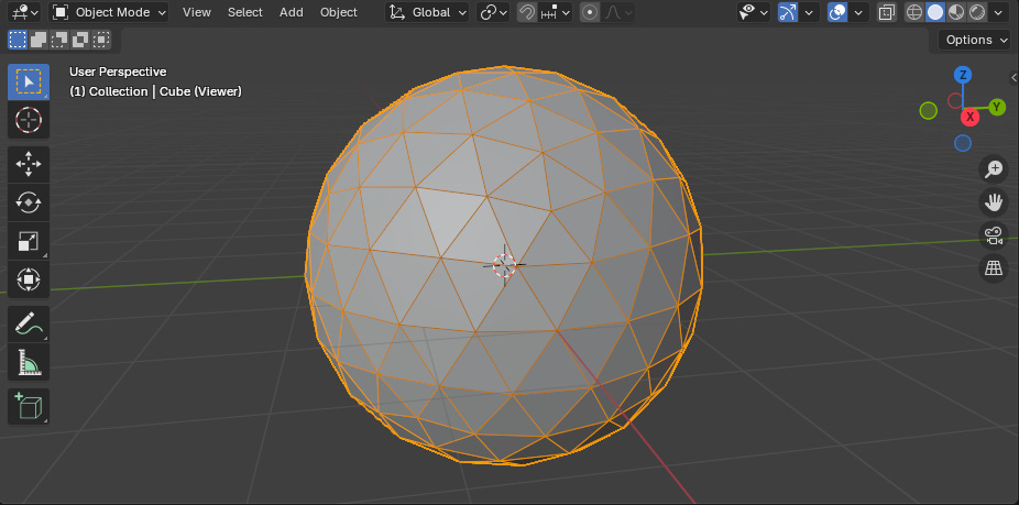
Disconnect the Group Input node from the Group Output, and insert an Ico Sphere node (Hint: “Ctrl+Right Click Drag” disconnects nodes). The values don’t matter too much, but you’ll want at least a couple of subdivisions to see the results. I went with 3.
Step 2
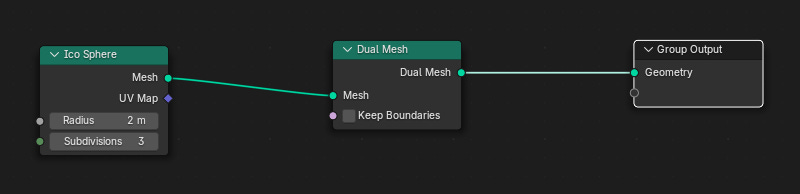
Now lets convert our triangular mesh into hexagons.
Place down a Dual Mesh node and connect the Mesh output socket on the Ico Sphere to the Mesh input on the Dual Mesh node.
Step 3
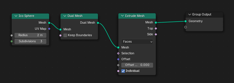
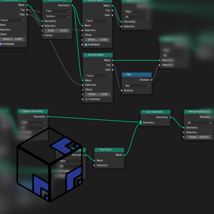
Then we’ll create our hexagonal frame by extruding every face without applying an offset to move the faces.
Place an Extrude Mesh node after the Dual Mesh node. Connect the output of the Dual Mesh node to the Mesh input socket of the Extrude Mesh node. Adjust the Offset Faces socket (not the Vector Offset socket) to a value of 0.
Step 4
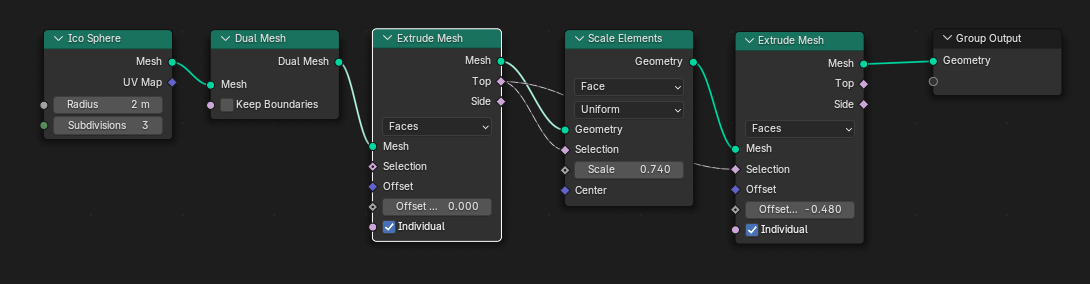
We’ll shrink the faces that we created in the previous step, and then extrude it again to push it inwards.
Place a Scale Elements node and another Extrude Mesh node after the first Extrude Mesh node. Connect the Mesh sockets from left to right. Connect the Top Boolean socket from the first Extrude Mesh node into both of the Selection Boolean sockets on the Scale Elements and the second Extrude Mesh nodes. Adjust the Scale Value on the Scale Elements node to a number smaller than 1, but above 0.
Step 5
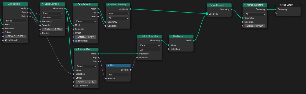
Now we could end right there, however if you look inside the hexagonal ball you’ll find that you don’t have any faces inside. Thankfully we technically already have those faces, but we need to first isolate them and then flip their orientation.
Place down a third Extrude Mesh node underneath the second. Connect the Geometry socketfrom the Scale Elements node into this third Extrude Mesh node, and connect the Side Boolean socket from the first Extrude Mesh into the Selection Boolean socket on the third Extrude Mesh node. Set the Scale Value socket on the third Extrude Mesh node to the same value as the Scale Value socket on the second Extrude Mesh node.
Then place a Boolean Not node and connect the Top Boolean from the third Extrude Mesh node into it. Place two Delete Geometry nodes in front of both the second and third Extrude Mesh nodes. Connect the Top Boolean socket of the second Extrude Mesh node to the Selection Boolean socket of the first Delete Geometry node, and the Boolean socket of the Boolean Not node into the Selection Boolean socket of the second Delete Geometry node.
Finally, place a Flip Face node in front of the second Delete Geometry node and connect the Mesh socket. Add in a Join Geometry node and connect both Mesh sockets from the Flip Faces and first Delete Geometry nodes. Optionally, place a Merge By Distance Node with just the Mesh socket of the Join Geometry node to weld the vertices together.
(Optional) Step 6
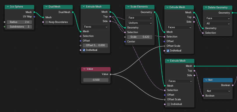
Place down a Value node and connect the Value socket to the Offset Scale Value sockets of both the second and third Extrude Mesh nodes. This allows us to only adjust one value, but affect the offset scale for both Extrude Mesh nodes.
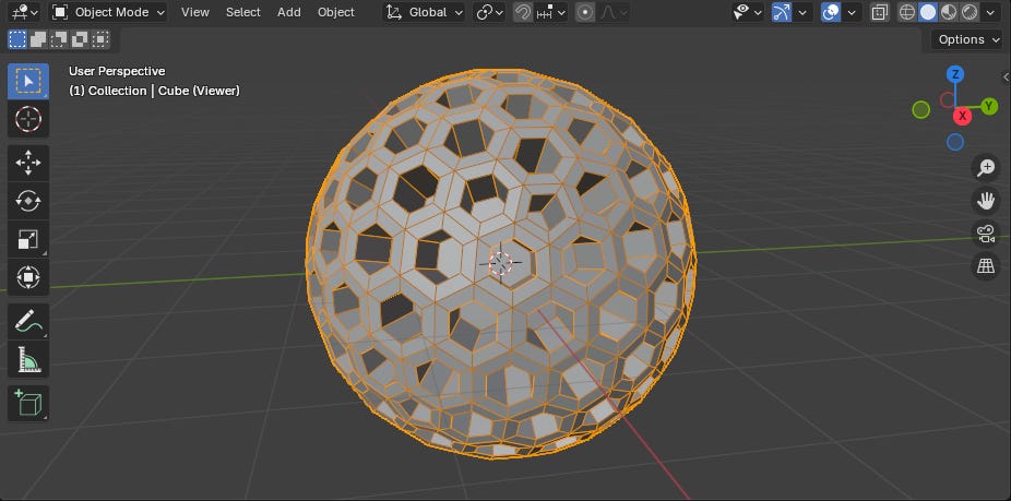
Final Result
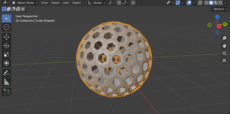
With the nodes connected, now you should have a hollow hexagonal ball that you can both make larger and smaller than the starting Ico Sphere due to the Value node we connected to both Scale Offset nodes.
Outro
This article has been a bare-bones introduction to Geometry Nodes in Blender 4.3, in which we covered:
Navigating the UI to access Geometry Nodes
Creating a Geometry Nodes Group
Placing Nodes within a Node Group
Connecting Nodes via Socketss
A basic workflow for working within Geometry Nodes
Next Week
Next week we’ll be taking a closer look at Fields by diving into Data Types, Node Types, and Node Functions. All the while highlighting some more commonplace nodes that you’ll be frequently encountering when working with Geometry Nodes.
Supporter Content
Finally, Supporters will receive a bonus How-To Guide for creating complex shapes and objects within Geometry Nodes on Monday, January 20th. It will include more details, more pointed instructions, and more insights into Geometry Nodes.
Make sure to subscribe to ensure you get full access to that guide or feel free to use a complimentary free viewing to check out MipMap’s paid content before you become a Supporter.
If you enjoyed this tutorial, please like and sign up for a free subscription to MipMap! Or, if you didn’t enjoy then leave a comment to let me know what I can do better for the future. Either way, thank you for reading MipMap!
- Adam
I mistakenly grouped all Sockets as Fields, when Fields are a mostly separate topic. I’ve since corrected all references to Fields and replaced them with Sockets to make sure that everything is correct. See Next Week’s Article for more information about Fields.