How To Procedurally UV Procedural Meshes
Shortest Edge Path Node, Semi-Tri-Planar Mapping, and More Procedural UV Techniques
Geometry Nodes' power comes from the iterative process. By placing one node after another, you can build bridges, construct buildings, or create eldritch abominations only found in your deepest nightmares. And if you aren't satisfied with what you've got you can simply tweak some of the settings and get a whole new result.
Unfortunately we can't keep placing nodes ahead of nodes all the way down to the moment we render. Not yet at least. Geometry Nodes run out of space to breath as soon as you move past the modelling stage. While this won't always be the case, we have to know where the boundaries lie so that we as artists can make best use of our tools.
As I mentioned above, Geometry Nodes isn’t so useful beyond the modelling stage. And if you remember my series of the asset creation pipeline last September, then you'll know that after modelling comes UVing. Fortunately, Blender's developers have given us a node that encompasses the entire UV unwrapping process, meaning Geometry Node is still of use to use. It isn't a straightforward process though. Instead, we have to do some heavy lifting in order to get a procedural unwrap that works in our favour.
UV Unwrap Node
The UV Unwrap Node is a clean-cut copy of the Unwrap Operator that exists in manual modelling workflows. If you place the node down in your node graph and hook up your mesh into all the right sockets, you'll get an output that looks exactly like if you hit "U" and clicked "Unwrap" from the menu in the viewport.
If you've performed UV unwrapping with Blender's default unwrapping tools, you know that there is a lot to be desired. But since we're working with Geometry Nodes, we're able to go back throughout the node graph and collect a number of values and fields to help us unwrap the model exactly the way we want it.
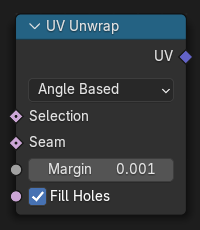
The node itself has four sockets to input information into.
"Selection" - Takes in a boolean value that determines which faces will be unwrapped.
"Seam" - Takes in a boolean value that determines which edges will be used as seams for the unwrap.
"Margin" - A float value that determines how much space will be put in between each UV island during the Island Packing operation.
"Fill Holes" - A boolean toggle which controls whether any holes in the mesh will be filled to better avoid overlaps and preserve symmetry.
As well, this node only has one output socket which returns a UV vector field value with the UV coordinates of our newly generated UVs.
Controlling The UV Unwrap
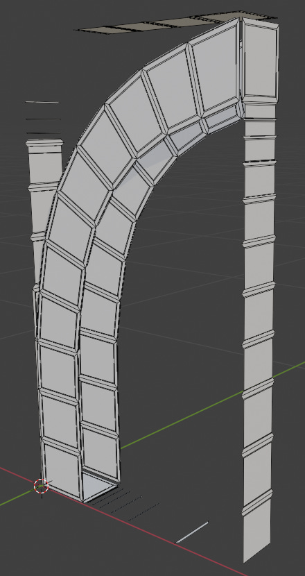
In order to UV unwrap our procedural mesh, we technically don't need to connect anything except the UV Unwrap Node. However, as I outlined above, this won't give us the amount of control we're looking for. To get more control over the look of our UVs we have to go deep into Geometry Nodes. In this guide I'll be showing three different techniques, two of which will be shown on our archway model we made a couple of weeks ago, while the last will be a link to a fantastic video that is purely procedural.
Shortest Edge Paths
This method uses a Shortest Edge Paths Node setup to find the fastest way from one vertex to another as specified by the amount of vertices it has to cross to get to the end. By specifying the start and end vertices, Blender will find a line that will act as our seam, allowing us to use those segments to cut the mesh. We can also add in additional seams using Boolean math to make multiple seams at the same time.
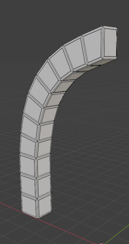
An example is shown here where a line is created along one edge of the archway in combination with using different boolean groups created by the Extrude node and a Vertex Neighbor node.

Quasi-Tri-Planar Mapping
Tri-planar mapping is a technique use to generate UVs without designation seams and creating maps. It uses the face normals to designate what material is mapped to the face.

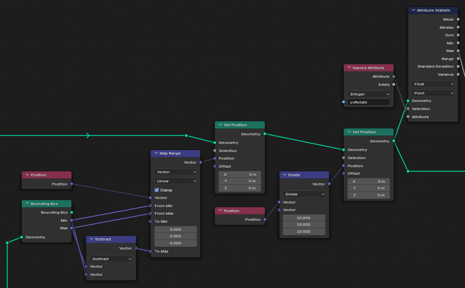
I've created a setup that takes inspiration from this method, although it's not truly tri-planar mapping. Instead, we flatten the mesh's faces using a Raycast Node that shoots towards a bounding box from a given face. When the ray hits a face, the face is separated into a specific group. Then the faces are flattened against that bounding box, and arranged so that they fit into a single plane.

After this we can simply convert the actual 3D coordinates to 3D UV coordinates since we aren't utilizing one of the dimensions. It's a bit shaky and needs some refinement, but the underlying concept is what's important.

Node Setup (Very Involved)


Actual Planar Mapping
This video by Entagma illustrates the actual process of planar mapping. As opposed to my method above, this method directly utilizes the direction of each faces normal to split the mesh into halves. Then both sides are UV unwrapped before being stitched back together.
Since this video was made for Blender 3.3, the way that the UVs are captured will differ slightly than what was in the video. Instead of setting up an output for the Geometry Nodes modifier, we can directly store the UVs in a Store Named Attribute Node set to the Face Corners domain and a 2D Vector value. Then, all we need to do is make sure that the material we create in the Shader node graph has an Attribute node set to the same name we gave the Store Named Attribute Node. Plugging this into the Vector input of your texture will output the stored UV values that we created inside of the Geometry Nodes.
Applying Materials
As a final step, if we want to see how materials will look on our procedural geometry, we can place down a Set Material Node and select the desired material. This way, we can designate which material to set for specific faces thanks to the Selection field input socket on this node. It isn't possible to assign materials the normal way to geometry nodes unless you apply the node modifier. Be aware though that this will remove your ability to make edits to the node graph once the modifier is applied. Also, the Set Material Node can't be used on instances of geometry. If you have instances, make sure to realize them with a Realize Instances Node, or just apply a material to the mesh before you instance it.
Outro
In this guide we went over UV Unwrapping in Geometry Nodes for Blender 4.3. After reviewing the UV Unwrap Node itself, we took a look at three methods for producing the desired unwrap effect. The first was a manual selection of which edges we want to designate as seems. I showed off a custom option for the second that takes inspiration from the tri-planar mapping technique. The last method was a video that is directly taken from planar mapping techniques, directly using the normals to unwrap a meshs UVs. Finally, we briefly went over applying materials to procedural meshes using the Set Material Node.
Procedural UVing is a very straightforward process, but it can be as simple or as intricate as you wish it to be. Hopefully you’re able to take away some new insights from what I’ve shared, and if you’ve made something cool let me know!
- Adam


