

How To Build Custom Shapes & Objects In Geometry Nodes
Build Custom Curves, Create Faces From Scratch, and Align Vertex Normals in Blender 4.3

Procedural workflows might adhere to the same limitations as hand crafted work, but they require a separate way of thinking. Instead of building up detail from low poly to high, we have to think like we're building with Lego. The final model is just a bunch of components and steps that we have to figure out how to reproduce. We don't have any kind of instruction booklet though, no guide to help us with every step. If we want to make something, it's up to us to figure out how we get there.
For some, this challenge goes completely against what art is all about. There isn't a flow that comes with figuring out node connections, nor any happy accidents that, while not overtly contributing to the final product, help distinguish one's work from someone else's. But I beg to differ. For me, proceduralism isn't about finding a creative passion inside of code and nodes. It's about the end product inspiring me to go even further, to push my abilities (and the software's abilities) as far as they'll go. But in order to get inspired, we have to start with the building blocks.
In this guide we’ll cover the following:
Create Custom Curves By Manipulating Vertex Positions
Override Vertex Normals For Correcting Extrusions
Generating New Faces From Selected Vertices
With that said, let's move onto today's guide. As an aside, Substack might compress the photos that I post here, so in case anything is unintelligible, Here is a link to an Imgur post that should let you see everything in it’s original resolution. Let's get started.
Build Custom Curves
The basis of building proceduraly lies in assembling shapes. Therefore, if we want to utilize Geometry Nodes to it’s fullest extent, we need to know how to make the shapes we want.
Let’s start with a simple curve. In regular modeling workflows, we’d start with a Bezier curve and place the control points in the desired spots. Then we’d adjust the anchors to get the right curve. Two steps, easy as. With Geometry Nodes, we need to do a bit more work to get the same effect.
To start, we need a curve object, either a Mesh Line or another type of Curve primitive that has points we can manipulate. In order to manipulate the curve, we need to think about how we want the curve to move. We'll be going for a simple arch, which gives us a lot of options. In this guide we’ll be using a Float Curve node to drive the profile of our curve, however you should be able to use any mathematical formula to move the points.
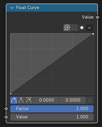
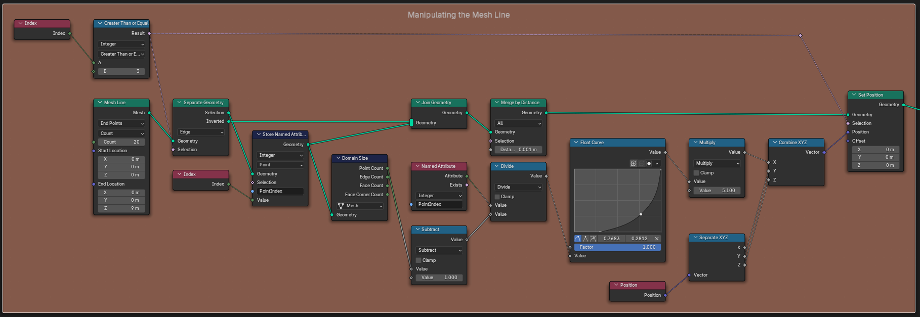
The Float Curve node allows us to designate a profile that will drive the distance our curve points move on a specific axis. We can use a setup like the one below to accomplish this.
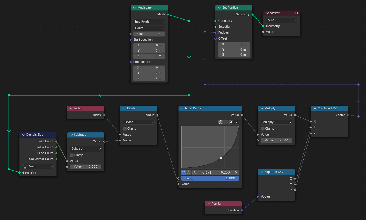
If we designate more points on the Float Curve’s graph, the curve will follow that profile to the best of it’s ability (which is determined by it’s resolution, or amount of points in the curve object).
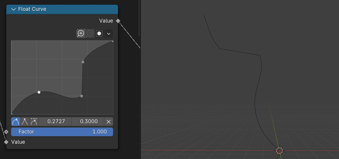
Finally, a setup like the one below will allow us to control how many points along the curve object will be influenced by the Float Curve. This allows us to shift the curvature upwards while keeping the same curve object.
Align Normal Directions
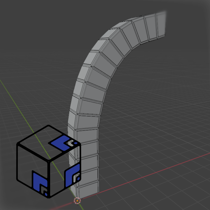
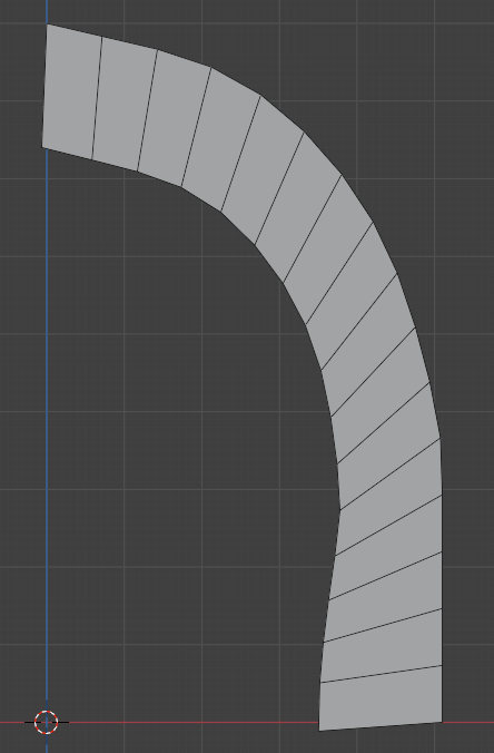
Now that we have control over our curve, we need to utilize it. For this guide, we’ll be turning this Mesh Line into a pillar that you might find in a bridge or an archway.
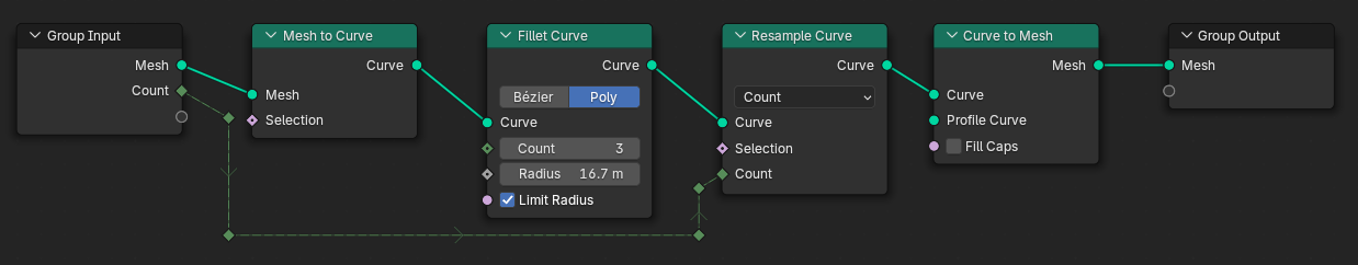
First, we have to even out the distribution of the points on our Mesh Line. Using the profile of the Float Curve merely pushed the points in the X axis, but our edge length is very skewed. Use the setup in the photo below to convert the Mesh Line to a proper curve in order to resample it and evenly distribute the points.
At this point, it might be tempting to just plug the Mesh Line into an Extrude Mesh node and call it a day. However, doing so reveals that the direction of our Normals is not what we want. Because the Normals of the Edges in our Mesh Line are an average of the Point Normals, we won’t be able to easily get them extruding in the direction we want. Instead, we’ll be extruding the Vertices in the direction we want, and then constructing new Faces based on those Vertices.
But first, we need to manually adjust the direction of the Vertex Normals on our Mesh Line. The photo below will contain the full node setups for achieving this, however make sure to read the steps below to fully understand what is happening here.
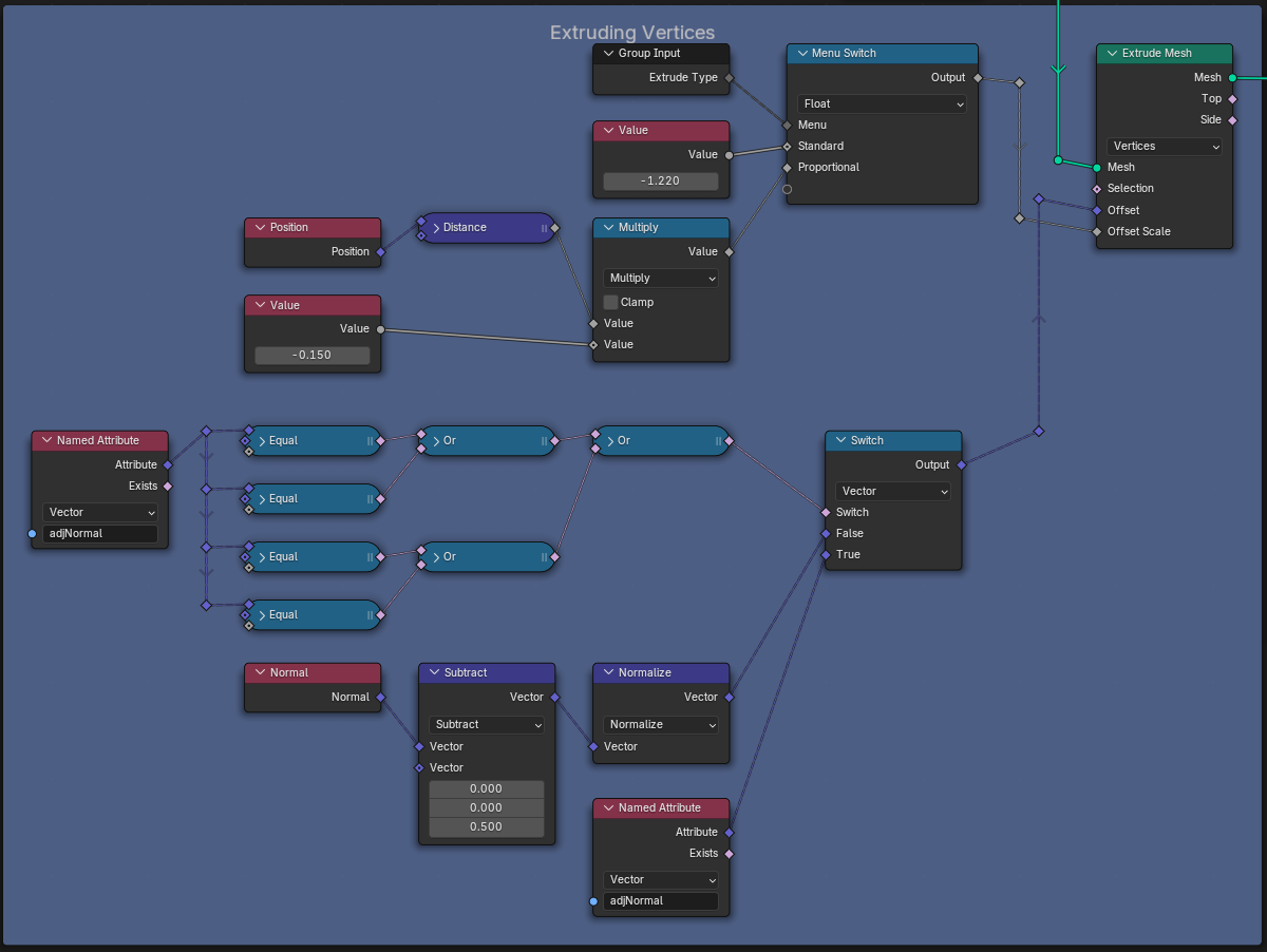
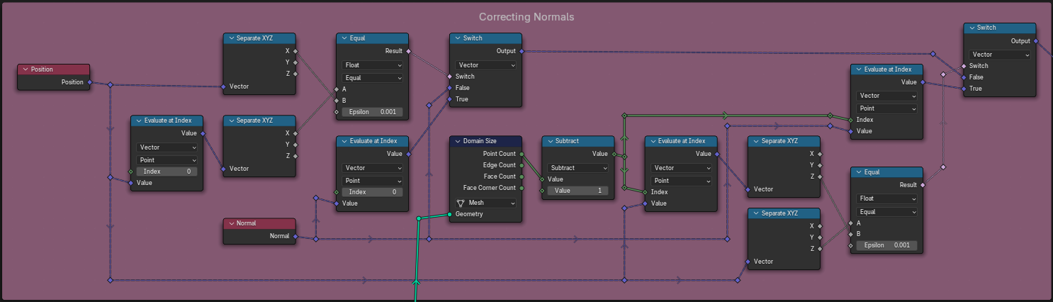
There are 2 main processes happening here. The 1st is picking a custom point for the Vertices to point towards, and the 2nd is manually correcting the Vertex Normals for any Vertices that happen to align with our first and last Vertices. This last step is required for those who implemented a control on how many Vertices were influenced by the Float Curve profile in the first section.
Process 1: Extruding The Vertices
Set the Extrude Mesh’s drop-down option to Vertices instead of Edges.
Connect your Resampled Mesh Line to the Mesh input socket of the Extrude Mesh node.
Place a Normal Field node, a Vector Math node set to Subtract, and a Vector Math node set to Normalize down.
Connect the Normal Field output socket to the first Vector input socket on the Subtract node.
Connect the Vector output socket on the Subtract node to the Vector input socket on the Normalize node.
Change the second Vector input socket parameters on the Subtract node to the XYZ coordinate where you’d like the Mesh Line Vertices to point towards.
Connect the Vector output socket on the Normalize node to the Offset Vector Field input socket on the Extrude Mesh node.
Process 2: Correcting The Vertex Normals
Place down a Position Field node, 2 Evaluate At Index nodes, 2 Separate XYZ nodes, a Compare node set to Equal, a Normal Field node, and a Switch node set to Vector values.
Plug the Position Field output socket of the Position node into the Value input socket of the first Evaluate At Index node and the Vector input socket of the first Separate XYZ node. Make sure that the Index parameter of the Evaluate At Index node is set to 0.
Connect the Value output socket of the first Evaluate At Index node into the Vector input socket of the second Separate XYZ node.
Connect the X output socket on both Separate XYZ nodes into the A and B input sockets on the Equal node. Make sure the Equal node is also set for Float values.
Plug the Result output socket of the Equal node into the Switch input socket on the Switch node. Make sure the Switch node is set for Vector values.
Plug the Normal Field output socket of the Normal node into the Value input socket of the second Evaluate At Index node. Make sure that the Index parameter is set to 0.
Connect the Value output socket of the second Evaluate At Index node into the True input socket of the Switch node.
Connect the Normal Field output socket of the Normal node into the False input socket of the Switch node.
This second set of steps corrects the Normals of any Vertex that has the same X positional value as the first Vertex. Meaning that all of the Vertices that point straight up will all point in the same direction. If you’d like to do the same for any Vertex that has the same Z position as the last Vertex (i.e. all of the Vertices that go straight across will all point the same way) do the following:
Repeat Steps 1-7 of the previous instructions.
Place down a Domain Size node and an Integer Math node set to Subtract.
Connect your Resampled Mesh Line to the Geometry input socket on the Domain Size node.
Plug the Point Count output socket of the Domain Size node into the first Value input socket on the Subtract node.
Connect the Value output socket of the Subtract node into the Index input socket on both the third and fourth Evaluate At Index nodes.
Connect the Output Vector socket of the first Switch node into the False input socket of the second Switch node.
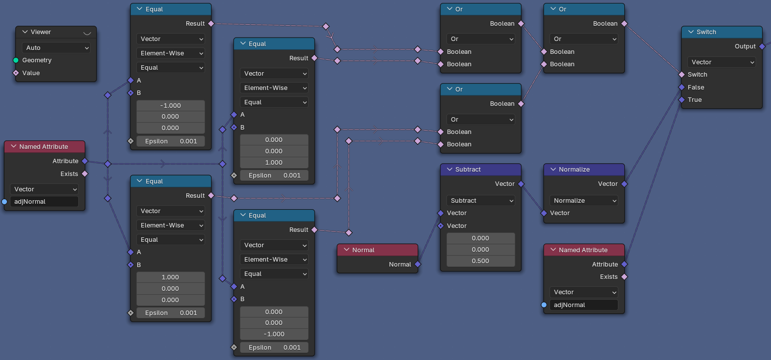
Place down a Store Named Attribute node and connect your Resampled Mesh Line to the Geometry input socket. Change the first drop-down item to Vector values, and make sure the second drop-down item is set to Points.
Connect the Output Vector socket of the second Switch node to the Value input socket of the Store Named Attribute node. Make sure to create a new name for this value in the Store Named Attribute node.
To utilize our manually adjusted normals, we have to alternate between the adjusted normals and the pointed normals. The following photo shows a brute forced way to do so, however I’m sure there are better ways to achieve this. Note that the Named Attribute nodes should be filled with the name you set in the Store Named Attribute node in the steps above.
Generate New Mesh Data
Finally, the last task is to turn these extruded vertices into actual mesh faces. Unfortunately we have to get creative in achieving this since Blender doesn’t come with a built-in method for creating faces. However, it does give us the Convex Hull node, which creates faces based off of a series of Vertices you provide it. With the addition of a Repeat Zone (which we’ll be covering more in-depth in the next tutorial) we can iteratively create each face based on the selection of Vertex IDs.
Unlike the last section, I do not think I’m going to be able to describe the step-by-step process. There is just way too much happening. Instead, I’m going to provide a large picture of the node setup, and then explain some of the intricacies.
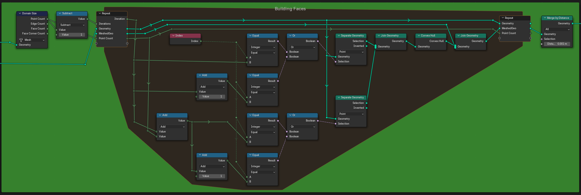
The Domain Size node needs to be connected to the Resampled Mesh Line geometry instead of the output of the Extrude Mesh node.
This controls how many iterations the Repeat Zone goes through, and since the Extrude Mesh node created a second Vertex for every Vertex we already had, we can use it as our counter.
The initial Geometry, along with the Created Faces geometry and Point Count integer need to be passed back out at the end of the Repeat Zone.
We add the Iteration value to our Point Count so that we can connect each Vertex to its Extrude Mesh pair. The Created Face for each Iteration gets added to all of the previous Iteration’s Created Faces. The initial Geometry is just what gets sampled every iteration without being changed.
Do not use the initial Geometry output socket at the end of the Repeat Zone, use the Created Faces geometry output socket.
Since we aren’t modifying the initial Geometry, it’ll come out the other end of the Repeat Zone the exact same.
Outro
The only parts of the node group that I’ve left out have to do with aligning face normals, basic extrusions, and scaling certain elements. If you’ve followed my Geometry Nodes series up until now you should certainly be able to recreate this by yourself. I have full faith in you!
Otherwise, that’s the end of the first How-To for MipMap. How was it? Anything you feel needs to change? Let me know in the comments below, and thanks for reading! I hope you enjoyed, and we’ll see you later this week!
- Adam