

Blender Basics: Texturing
MipMap #034: UDIMs, UVs, & Vertices


You’ve modeled your heart out, moved all of your polygons to exactly where they’re needed, and even applied all of the relevant modifiers.
And now you have an uninspiring gray blob of an object.
If this was as far as Asset Creation went, then nobody would want to look at anything digital ever again. Fortunately though, 3D artists have been able to turn their gray blobs into stunning pieces of art ever since computer graphics were a thing.
Texturing is the process in which we take our polygon meshes and project a series of images across all of their lovely little faces. It’s how we add colour, make certain parts shiny and reflective, and impart all of the small little details that are way too impractical to manually add to the model.
We aren’t just adding images though, in fact there is a whole workflow specifically dedicated to Texturing (and it even spans across DCCs). Let’s discuss.
On Projecting
The core concept at the heart of Texturing is that your game object is (likely) a polygon mesh with at last several faces. Those faces can be “unwrapped”, where certain edges are designated as “seams” to then lay out every face in a 2D plane. We can do this because of some complicated math that happens behind the viewport, but we can think of it like breaking down a cardboard box. While it appears like a 3D object, in reality it’s just one 2D sheet of cardboard that’s been folded and taped.

Once we’ve unwrapped our polygon mesh, now we have a set of 2D faces in a U and V axes (as opposed to the X, Y, and Z axes we work with in 3D). Coincidentally enough, images also live in a 2D format. Through some more hidden computer math we can project an image over top of our unwrapped faces and display the image on the faces that it overlaps with.
That is the gist of Texturing. However, there is a lot more to understand in order to bring our objects from gray blobs to photo-real assets.
Texturing Key Concepts
UVs
Just like the XYZ axes in the 3D scene have units associated with them, so does the UV axes. The workspace that an unwrapped mesh sits in exists from 0,0 to 1,1, a perfect square area called the UV grid. While you can move your mesh islands (the little groupings of faces in the UV space) around the UV grid, if you put them outside of the 0,0-1,1 bounds you’ll just wind up back where you started. Past the edges of the grid, the UV space repeats itself (unless we specify otherwise).
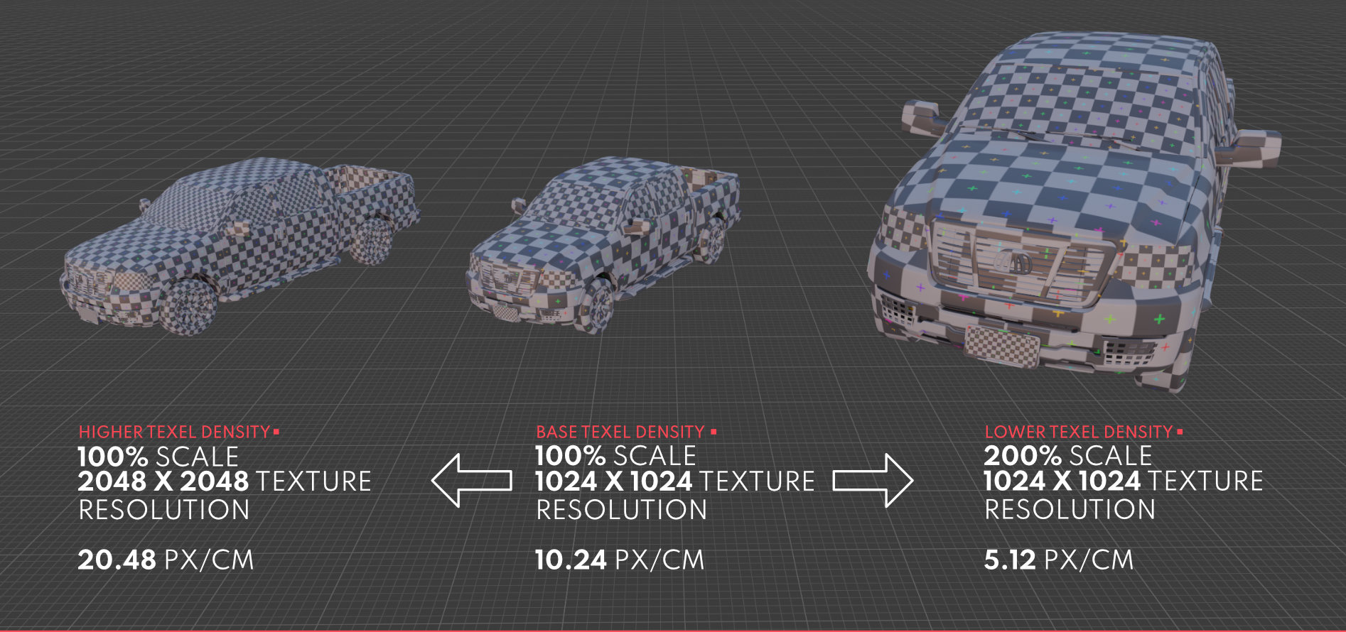
Texel Density
Since we are able to project an image onto our faces, we now encounter several restraints. Images have set resolutions, which means that the size of our UV islands correlates to how many pixels in the image get displayed on the mesh. This is known as Texel Density, or the amount of pixels per centimeter or meter. The unwrapped faces of a 3D box that is 5x5 meters can fill the same UV space that the faces of a 0.25x0.25 meter 3D box can. However, if we account for Texel Density we can scale our UV islands and image resolutions so that everything matches visually.
UDIMs
However, sometimes we’re confined to only using images of a certain resolution or our mesh is just too big to fit nicely within a single UV grid. UDIM tiles address this issue by allowing you to space out your UV islands on multiple UV grids. Remember how I said that if you move a UV island beyond the 0,0-1,1 space it’ll just repeat? Not if you specify that you are using UDIMs. Enabling UDIMs is a per-DCC process, but within Blender it’s simply specifying that the image you’re importing is an Image Sequence and making sure that the other tiles are all in the same directory.

Materials
Materials are the end product of the Texturing process. A polygon mesh can have multiple materials applied to it, and we can specify which faces have a certain material applied to them. Materials generally come with several slots to attach images and other values into to better create the final look you want.
In Blender, the default Material contains a “Principled BSDF” shader which allows for a whole host of inputs to better achieve a photo-real style. However there are other shaders for working with NPR and other stylized art styles.
Image Maps
An Image Map is a specified function of a Material. Diffuse maps determines the initial colours, Normal maps determine visual deformations that aren’t destructive to the mesh, and so on. Here’s a list of the common Image Maps you might work with:
Diffuse
Dictates the initial colour of an face without input from the lighting. Utilizes the three RGB channels of an image.
Roughness / Specular
Determines the reflectivity of an object. Higher values (white colour) are more rough, while lower values (black colour) are more reflective. Uses a single grayscale value (0.0 - 1.0), thus can be packed into a single image channel.
Metallic
Determines the metallic value for a Material. Again, higher values are more metal, lower values are less. Also uses a single grayscale value and can be packed into a single image channel.
Normal
A means of telling the Material how light interacts with the face. Small surface imperfections like scratches and dents can be implemented without modeling using a Normal Map. Uses the three RGB channels of an image.
Ambient Occlusion
Tells the Material what areas are more shaded than others. Helpful is tandem with the Normal map to give the illusion of depth when there physically isn’t any. Uses a single grayscale value and can be packed into a single image channel.
Alpha
Determines how opaque / transparent the Material is. Higher values are more opaque (solid), while lower values are more transparent (see-through). Uses the Alpha channel of an image, can also be packed into another single channel.

via CGTricks

Channel Packing
Images can get stupidly big, even when we compress them and package them for games. Saving space where we can gives us every little bit of additional performance. So when I specified how many “channels” each map uses, we can then make use of how images are assembled.
In basic terms, the images we see are made up of a red, green, blue, and sometimes alpha channel. These channels are actually just grayscale images with a value between 0 and 255 per pixel that says how much of a given colour is in that pixel. When you combine all of them together, you get the final image. For Diffuse maps, these work by default since we need all 3 or 4 channels. But if we want to get tricky, we can take some other values (like Roughness, Metallic, and Ambient Occlusion) that only require 1 colour channel, and smash them together. 3 images worth of information for the price (size) of one.
You can also go further and compress multiple single-channel images into a single image, however that is beyond the scope of this article and mostly unnecessary for the average developer.
Procedural Textures
But what if you don’t have a set of textures, or you need a way to differentiate between the ten instances of the one barrel you made? Add in a little bit of procedural generation. With Procedural Textures, we’re essentially creating the images within the DCC rather than importing an image. All Image Maps can be replaced by Procedural Textures, but in most cases you’ll want specific images. At the most basic level, Procedural Texturing comes down to laying different patterns or noise to create the desired look.

Where it comes in handy most often is in differentiating between different objects in a scene that all use the same base mesh and image maps. You can tie the location of an object to the seed of a noise or pattern that is then laid on top of the original Material. As long as it’s not too noticeable, you’ve just created an endless amount of variation for little-to-no extra work.
Texture Baking
Texture Baking is the process of taking an object and “baking” an external type of information to an image. Common examples are taking either a super detailed high-poly version of a mesh and transferring some information to the low-poly version (like small sculpted details on the high-poly to the Normal image of the low-poly), or by taking some Procedural Textures and transferring how they’ve been displayed across the mesh onto a selected image. Be aware that this can be intensive, and the higher resolution the desired baked images, the more intense the process will be.
Vertex Painting
While not formally being attached to the Texturing process, Vertex Painting is an additional process that can also add additional depth and detail without physically changing the model, or even a Material attached to the model.
Essentially, we are able to attach an RGB value to every Vertex on a mesh, often times by literally “painting” the value on with a brush or some other operation. These values can either be directly plugged into a Material as a mask, or can be baked out for the same use in other DCCs if the Vertex Data doesn’t persistent across DCCs.

As a result, we can mix several Materials together across faces without being restricted to one Material per face. If we’ve painted on one Material in the Red Channel, a second in the Green channel, and a third in the Blue channel, then we now have masks that tell the DCC or renderer what Material is shown at what spot. And if we don’t want to keep them as separate channels, then we can just bake out the relevant images so that we only have one set of image passes to deal with instead of three.
Trimsheets
Last, but certainly not least, are Trimsheets. These are more used in environment design rather than for characters or props, but they can still have their uses in those cases as well.
A Trimsheet is a set of Image Passes that can be infinitely tiled without any breaks or interruptions. Typically these are accomplished by choosing either the U or V direction and ensuring that the created texture doesn’t have show any seems on that given direction. Thus, if we had a super long face that we can’t subdivide or break up, we can simply align it with our Trimsheet and have the image repeat without any seams or imperfections.

Creating Trimsheets requires a decent amount of planning, so I will be linking to guides on how to make them in the next section.
Resources and Tutorials
The fun part of the article where I get to link out to all of the resources that expand on what we’ve just discussed. Fortunately, the different steps of the Asset Creation workflow cascade into each other so there’s even a video from last week’s article that goes into some of what was discussed today.
Beginner’s Guide to UV Unwrapping
UV Unwrapping Techniques
Blender’s Principled BSDF Material
Texture Baking
Channel Packing
Trim Sheets
Outro
Another week, another section of Blender further unveiled. With only Rigging and Animation left, I'm not sure whether to continue on with an Advanced Blender series, or maybe to move into giving Unreal Engine the same treatment? Regardless, I do have some fun new ideas that I will be looking at unveiling closer to the end of September, so stay tuned for that!
Until next week, stay unwrapped!
- Adam